This guide is designed to help you in your journey to building the perfect transition. To use this software you must acquire up to seven different measurements.
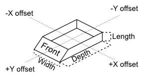
- Width: Measured from the left ⭤ right edges of the front or back face of the duct
- Depth: Measured from the front ⭤ back edges of the left or right face of the duct
- Length: Measured from the bottom to top of the duct
- Offset X: If you are facing the front of the ductwork, this is the offset which moves left ⭤ right. You may also call this “Offset Width”
- Offset Y: Facing the front, this is the offset which moves towards or away from you. Also referred to as “Offset Depth”
- Transition Width & Depth: Same as the above, but referring specifically to the destination
When designing a duct in FieldFab, you will be viewing the ductwork as if it were in the up flow position. This means Transition Width and Transition Depth will be the upper edge. Below is an isometric drawing illustrating the measurements as you would enter them. This drawing is also available inside the help sheet of the settings tab in the app.
Ductwork without offsets are symmetrical in nature. Once you add offsets, the overall length and width of a specific face changes. Therefore, width and length of the cutting lines change. Below you will find the effects of offsets as they’re applied to the front and left faces of the duct you are building.
One of the most common configurations for ductwork is to have one or two sides be flat – usually when a furnace is against a wall, so for that all you have to do is press and hold on one of the faces and it will give you the option to make that side flat.
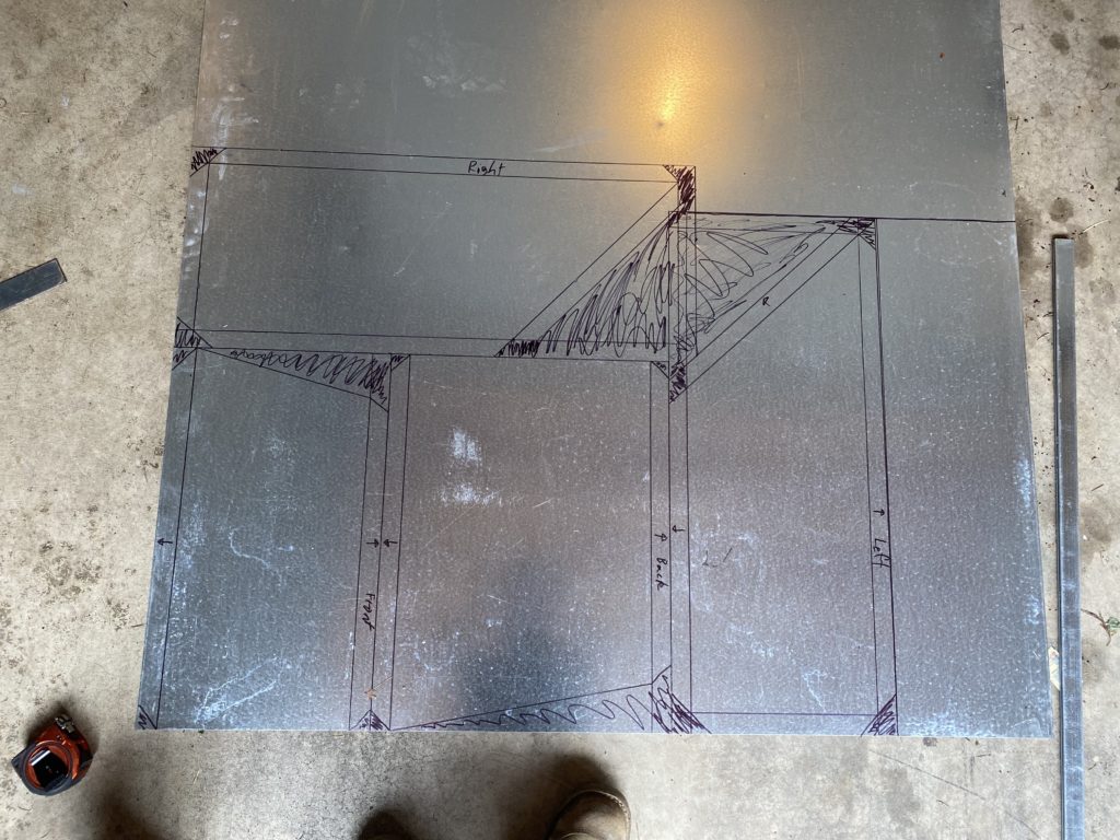
Once you have the desired measurements you can add tabs. The 2D view will show your tabs before folding and tapering is applied, and will also show the overall width and length of the face. The 2D view shows the face as if you are looking at it from the outside, so if you are folding an edge inward, you would fold the edge away from you. It’s important to draw the cutting lines exactly as you see them in the 2D view, but without marking the middle of the faces, as the markings will be visible!
Not only did I make this app, but I use it every day out in the field doing Retrofit for all kinds of different HVAC systems. If you have any questions or feedback to improve the workflow you can contact me at any time at robert@fieldfab.net